Some parts of my game have an isometric 2D view to them. I decided to try using Direct2D to draw those parts of the game. Under the covers, Direct2D uses Direct3D, and despite an extra layer, I figure it’s probably more efficient to do it this way because each object only has to draw 2 triangles instead of the 1,000s that each model includes. In theory, this will allow me to draw more objects, or attain a higher frame rate on lower spec video hardware. It’s also possible I’ve made the classic mistake of premature optimization, but I onto my adventure.
Initially I drew my objects in 3D in Blender, set up several carefully placed cameras around my objects at various angles, save the render output, and carefully translate various locations on the object. Since the ground presented to the user looks square, I also needed to distort the object so that the base had the right shape when viewed at 45 degrees. There were a several problems with this approach. 1) I have to re-render my objects every time I change a model in Blender. Eventually near the end of my project I plan to have a real artist re-do all my art (my “programmer art” is mediocre at best), and that sounds like a lot of costly work that will need to be done later. 2) I am drawing more and more objects, and the process is getting tedious. 3) objects like my robot need to be rendered a lot of times since their movement is animated. 4) to look good on various displays, I need several sizes of render output.
This is a perfect job for a tool, and thus I embarked on building a small tool that would load up my model, scale it and render it at various angles and in different poses, and sizes, ideally translate the locations on the object, and lastly save the results as a bitmap. Perhaps, if it’s more efficient, I can even do this rendering at startup. I’ll start with the tool.
The first step was to read the model that Blender created. I turns out the native blender file is binary, and the documentation doesn’t look super easy to follow. Next I looked at all the formats that blender would export to. Some of them didn’t support textures or poses. The COLLADA format looked like the past of least resistance, it was XML, it supported models, poses and textures, it’s supported by other 3D modeling programs, and there was some documentation.
After a couple of days, I had the model rendering in my little tool. It was, however, missing triangles. Not again !
I had a bunch of theories about what I did wrong. My first theory was, of course that it was the same problem as last time — I was specifying the vertices of the triangle in the wrong order. Triangles have a front and back, and they are not drawn when their front is facing away from the camera. The vertices need to be drawn clockwise around the intended normal of the triangle. The COLLADA format does include the intended normal for the triangle, but perhaps I needed to order the vertices properly during the import of the model.
I embarked on much re-learning of my university math to determine if my 3 vertices were going clockwise around the normal. After getting my math wrong several times, I eventually discovered that the exported vertices were perfectly ordered ! My new vertex sorting code was therefore unnecessary.
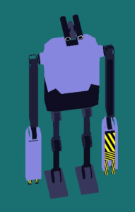
My next theory was that polygon (non-triangle) surfaces were not being exported. I changed the polygon on the right side of the robot from a rectangle to two triangles. The two triangles still did not show up.
Perhaps there were bugs in how I was handing the triangles to DirectX. I tried removing some triangles. I tried re-adding the triangles multiple times. They would not show up. I knew I’d eventually figure it out, but I was running out of theories.
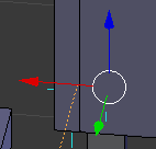
Next I tried looking at the coordinate system Blender and DirectX were using. I had previously noticed that “up” in Blender is the Z axis, while it’s the Y axis in DirectX. It was hard to miss with my robot laying on it’s back, and I had applied a -pi/2 rotation around X to my model to compensate. What I had not noticed was that in “left” in Blender is positive X, while “right” in DirectX is positive X. I suddenly realized my simple rotation around the X axis was not sufficient to properly adjust the vertices to the DirectX coordinate system !
I got to work on constructing a matrix to translate the vertices and normals correctly. Once I was translating the model correctly, a breakpoint in my code to ensure the vertices were being drawn clockwise started hitting. That made sense — the vertices are not necessarily going to be ordered correctly after the new translation.
My robot was still missing triangles, but something important was different. The missing triangle was now on the left side of the robot not the right ! All of a sudden, everything made sense. I was incorrectly translating the coordinates, and the robot was being mirrored on the X axis. This wasn’t obvious to me from the beginning because I’m unobservant, and the robot was symmetrical. I had tried to correct the right side of the robot by modifying the right side in Blender, but the left side in Blender had been rendered on the right side in my tool. I now modified the triangle on the left side (which was now rendering on the left side in my tool), and my triangle rendered !
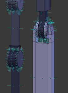
I am now busy correcting normals on my robot in Blender. If I had any artist training, I probably wouldn’t have made a model with normals facing the wrong way. On the bright side, I’m learning stuff ! There is a handy option in Blender that will draw a little stick away from the surface so you can visually see the normals, and then fix them if they’re wrong.